
Chapter 8
ANALYSIS OF MULTIPLE BODIES (NBODY>1)
Translation of the manual to HTML format can cause errors in file formating. Please see the PDF version of the manual for correct formmating.
WAMIT includes the capability to analyze multiple bodies which interact hydrodynamically and mechanically. Each of the separate bodies may oscillate independently with up to six degrees of freedom. (Additional generalized modes can be defined for each body, as described in Chapter 9.) The bodies may be freely floating, fixed, or constrained by external forces. The basic theory for multibody interactions with waves is similar to that of a single body as described in Chapter 15. The principal extension is to increase the maximum number of degrees of freedom from 6 for a single body, to 6N for N bodies (N is hereafter used to denote the number of bodies and the index K = 1, 2,...,N is used to denote each of the N bodies. ). For example, when two bodies are present the maximum possible number of degrees of freedom becomes 12, 6 for each body. In this example, modes 7, 8, 9 represent translation of body 2 in the direction of the x,y and z-axes of the coordinate system fixed on that body. These modes correspond to surge, sway and heave for the second body, respectively. Modes 10, 11, 12 represent rotation about the same axes. The extension of this convention to more bodies is evident. Thus, some output quantities are given in vector or matrix form with dimensions 6N or (6N) × (6N), respectively.
Separate GDF files must be input for each body, with their filenames listed in the POT file as shown in Sections 4.2. The individual GDF files for each body are unchanged from the case where N = 1, thus GDF files can be combined without modification to analyze multiple-body configurations. However the units of measurement, identified by the parameter GRAV, must be the same for all bodies. The program assigns GRAV based on the value in the GDF file for the first body (K=1). If the value of GRAV for another body differs from this by more than a small tolerance (GTOL=0.1) the run is terminated with an appropriate error message.
Except for the special cases described in Section 8.5, WAMIT assumes that there are no planes of hydrodynamic symmetry when N > 1. If geometric symmetry is specified for individual bodies, via their respective GDF input files, the program reflects about the corresponding planes and increases the number of panels accordingly. The total number of unknowns is the sum of the number required to describe each body, including reflections. Thus the run times and memory requirements are substantially increased.
When N > 1 walls can be defined using the procedure described in Section 12.4.
The multiple-body extensions are essentially the same for analyses based on the low-order and higher-order methods. However it is impossible to use both methods simultaneously for different bodies.
The GEOMXACT subroutines described in Section 7.8 can be used for multiple bodies, but special attention is required unless different subroutines are used for each body, or all of the bodies using the same subroutine have identical dimensions. Most of the existing GEOMXACT subroutines read in the appropriate dimensions from the GDF file in scalar form, to initialize parameters within the subroutine for subsequent calls. If the same subroutine is initialized again for another body, the dimensions are overwritten. As a result the dimensions in the last GDF file are applied to all of the bodies using the same subroutine. In cases where bodies with different dimensions are represented by the same subroutine, the dimensions used in subsequent calls should be saved within the subroutine as arrays with dimension NBODY. The subroutine FPSO12 in GEOMXACT illustrates this procedure for two FPSO hulls with different dimensions. A warning message is issued if two or more bodies use the same value of IGDEF in GEOMXACT.
There are three alternative ways to input parameters to the FORCE subprogram. Alternative Form 1 can be used for freely floating bodies, and the more general Alternative 2 Form can be used for bodies subject to external forces. Alternative 3 includes a Global Force Control file (GFRC) and a separate FRC file for each body, each being in either Form 1 or 2. These three alternative are described respectively in Sections 8.1, 8.2, and 8.3.
The POT file is as shown in Section 4.2, with the last three lines of data repeated in sequence for each body.
8.1 INPUT TO FORCE (IALTFRC=1)
Translation of the manual to HTML format can cause errors in file formating. Please see the PDF version of the manual for correct formmating.
If IALTFRC=1 the format of the FRC file is as shown below:
IOPTN(1) IOPTN(2) IOPTN(3) IOPTN(4) IOPTN(5) IOPTN(6) IOPTN(7) IOPTN(8) IOPTN(9)
VCG(1)
XPRDCT(1,1,1) XPRDCT(1,2,1) XPRDCT(1,3,1)
XPRDCT(2,1,1) XPRDCT(2,2,1) XPRDCT(2,3,1)
XPRDCT(3,1,1) XPRDCT(3,2,1) XPRDCT(3,3,1)
VCG(2)
XPRDCT(1,1,2) XPRDCT(1,2,2) XPRDCT(1,3,2)
XPRDCT(2,1,2) XPRDCT(2,2,2) XPRDCT(2,3,2)
XPRDCT(3,1,2) XPRDCT(3,2,2) XPRDCT(3,3,2)
.
.
VCG(N)
XPRDCT(1,1,N) XPRDCT(1,2,N) XPRDCT(1,3,N)
XPRDCT(2,1,N) XPRDCT(2,2,N) XPRDCT(2,3,N)
XPRDCT(3,1,N) XPRDCT(3,2,N) XPRDCT(3,3,N)
NBETAH
BETAH(1) BETAH(2) ... BETAH(NBETAH)
NFIELD
XFIELD(1,1) XFIELD(2,1) XFIELD(3,1)
XFIELD(1,2) XFIELD(2,2) XFIELD(3,2)
XFIELD(1,3) XFIELD(2,3) XFIELD(3,3)
.
.
XFIELD(1,NFIELD) XFIELD(2,NFIELD) XFIELD(3,NFIELD)
The only difference relative to the case of a single body (Section 4.3), is that the VCG and 3 × 3 matrix of each body’s radii of gyration are entered in succession.
8.2 INPUT TO FORCE (IALTFRC=2)
Translation of the manual to HTML format can cause errors in file formating. Please see the PDF version of the manual for correct formmating.
If IALTFRC=2 the format of the FRC file is the same as described in Section 4.4 for a single body, except that the array specifying (XCG,YCG,ZCG) is extended to include all bodies, and the external force matrices have dimensions NDFR × NDFR. NDFR= ∑ n=1N(6 + NEWMDS(n)) is the total number of degrees of freedom including all rigid body modes and generalized modes. The normal format is as follows:
IOPTN(1) IOPTN(2) IOPTN(3) IOPTN(4) IOPTN(5) IOPTN(6) IOPTN(7) IOPTN(8) IOPTN(9)
RHO
XCG(1) YCG(1) ZCG(1) XCG(2) YCG(2) ZCG(2) ...
... XCG(N) YCG(N) ZCG(N)
IMASS
EXMASS(1,1) EXMASS(1,2) ... EXMASS(1,NDFR)
EXMASS(2,1) EXMASS(2,2) ... EXMASS(2,NDFR)
.
.
EXMASS(NDFR,1) EXMASS(NDFR,2) ... EXMASS(NDFR,NDFR)
IDAMP
EXDAMP(1,1) EXDAMP(1,2) ... EXDAMP(1,NDFR)
EXDAMP(2,1) EXDAMP(2,2) ... EXDAMP(2,NDFR)
.
.
EXDAMP(NDFR,1) EXDAMP(NDFR,2) ... EXDAMP(NDFR,NDFR)
ISTIF
EXSTIF(1,1) EXSTIF(1,2) ... EXSTIF(1,NDFR)
EXSTIF(2,1) EXSTIF(2,2) ... EXSTIF(2,NDFR)
.
.
EXSTIF(NDFR,1) EXSTIF(NDFR,2) ... EXSTIF(NDFR,NDFR)
NBETAH
BETAH(1) BETAH(2) ... BETAH(NBETAH)
NFIELD
XFIELD(1,1) XFIELD(2,1) XFIELD(3,1)
XFIELD(1,2) XFIELD(2,2) XFIELD(3,2)
XFIELD(1,3) XFIELD(2,3) XFIELD(3,3)
.
.
XFIELD(1,NFIELD) XFIELD(2,NFIELD) XFIELD(3,NFIELD)
As in Section 4.4, the integers (IMASS,IDAMP,ISTIF) are set equal to one if the matrix follows, and equal to zero if no corresponding external matrix is included in the file. Omitting the matrix is equivalent to including the matrix with zero values for all elements.
The same format can be used with the external force matrices in separate files and with the corresponding filenames replacing the matrices in the FRC file. This option is specified by the values (IMASS,IDAMP,ISTIF)=2:
IOPTN(1) IOPTN(2) IOPTN(3) IOPTN(4) IOPTN(5) IOPTN(6) IOPTN(7) IOPTN(8) IOPTN(9)
RHO
XCG(1) YCG(1) ZCG(1) XCG(2) YCG(2) ZCG(2) ...
... XCG(N) YCG(N) ZCG(N)
2
MASS (filename containing inertia matrix)
2
DAMP (filename containing damping matrix)
2
STIF (filename containing stiffness matrix)
NBETAH
BETAH(1) BETAH(2) ... BETAH(NBETAH)
NFIELD
XFIELD(1,1) XFIELD(2,1) XFIELD(3,1)
XFIELD(1,2) XFIELD(2,2) XFIELD(3,2)
XFIELD(1,3) XFIELD(2,3) XFIELD(3,3)
.
.
XFIELD(1,NFIELD) XFIELD(2,NFIELD) XFIELD(3,NFIELD)
The separate external force data files MASS, DAMP, STIF contain a one-line header plus the three corresponding matrices shown in the first format.
The first line of this file, and all lines beginning with the variable NBETAH, are identical to the data in Alternative 1 FRC file. The data which differ in Alternative 2 are described in Section 4.4.
8.3 INPUT TO FORCE (IALTFRC=3)
Translation of the manual to HTML format can cause errors in file formating. Please see the PDF version of the manual for correct formmating.
Alternative Form 3 includes one Global FRC file (GFRC) and N FRC files. The FRC file for each body can take either the form of Alternative 1 or Alternative 2. With this option existing FRC files for single bodies can be used without modification. Note however that this precludes the consideration of external mass, damping and stiffness forces which produce coupling interactions between the bodies.
If IALTFRC=3 the input parameters in the GFRC file are listed below:
IOPTN(1) IOPTN(2) IOPTN(3) IOPTN(4) IOPTN(5) IOPTN(6) IOPTN(7) IOPTN(8) IOPTN(9) RHO
FRC(1)
FRC(2)
.
.
FRC(N)
NBETAH
BETAH(1) BETAH(2) ... BETAH(NBETAH)
NFIELD
XFIELD(1,1) XFIELD(2,1) XFIELD(3,1)
XFIELD(1,2) XFIELD(2,2) XFIELD(3,2)
XFIELD(1,3) XFIELD(2,3) XFIELD(3,3)
.
.
XFIELD(1,NFIELD) XFIELD(2,NFIELD) XFIELD(3,NFIELD)
The first three lines of this file, and all lines beginning with the variable NBETAH, are identical to the data in the Alternative Form 2 FRC file.
FRC(K) is the name of the FRC file for body K. The Form of each separate file must be 1 or 2, and this is specified by the optional array IALTFRCN in the configuration file, as described in the following section.
Some of the data given in N FRC files are read but neglected, if the same data is given in the GFRC file. For example, the data IOPTN and RHO in the FRC files for each body are neglected and the corresponding parameters provided by the GFRC file are used.
If fixed/free modes are specified for multiple bodies, using IALTFRC=3, the modifications described in Section 8.3 must be included only in the GFRC File and not in the FRC files.
8.4 PARAMETERS IN THE CONFIGURATION FILES
The configuration files described in Section 4.7 include several inputs that must be assigned separate values for each body. These include IALTFRCN, IGENMDS, IRR, NEWMDS, NPFORCE, NPNOFORCE, NPTANK, XBODY and XTRIM. The procedure for doing this when NBODY>1 is to indicate the index of the corresponding body in parenthesis, as shown below. If IALTFRC=3 the array IALTFRCN must also be specified with values for each body, unless the default values 1 are applicable for all bodies. A typical configuration file used for all of these parameters is as follows, with explanatory comments on each line:
IALTFRCN=2 1 2 (Form of FRC file for each body)
IGENMDS(1)=-1 (Body 1: IGENMDS=-1)
IGENMDS(2)=1 (Body 2: IGENMDS=1)
IGENMDS(3)=2 (Body 3: IGENMDS=2)
IRR(1)=2 (Body 1: IRR=2)
IRR(2)=1 (Body 2: IRR=1)
IRR(3)=1 (Body 3: IRR=1)
ITRIMWL=1 Trim waterlines for at least one body
NPDIPOLE(2)=(5-8) (Body 2: dipole patches or panels)
NPFORCE(1)=(1-4) (Body 1: integrate pressure on panels/patches 1 to 4)
NPFSP(4)=(4-4) (Body 4: free-surface pressure patch or panel)
NPNOFORCE(2)=(5-8) (Body 2: skip pressure on panels/patches 5 to 8)
NPTANK(1)=(8-11) (12-15) (Body 1: tank patches or panels)
XTRIM(1) = 1.0 15. 0. (Body 1 trim coordinates)
XTRIM(2) = 0.0 0.0 0.0 (Body 2 trim coordinates)
XTRIM(3) = 5.0 0.0 10.0 (Body 3 trim coordinates)
Some of these inputs are illustrated in the test runs TEST05, TEST13 and TEST13a described in Appendix A.
The array IALTFRCN specifies the value of IALTFRC for each separate body. The value of each element in this array must be either 1 or 2, as in the example above. If the number of elements in the configuration files is less than NBODY, the remaining elements are assigned the same value as the last input. Thus if NBODY is large, it is not necessary to define each element of the array explicitly. If IALTFRC is the same for all bodies, only the first body needs to be specified in IALTFRCN. The following alternative inputs are equivalent, for the case NBODY=8, to illustrate this rule in a situation where IALTFRC is not the same for all bodies:
IALTFRCN=2 1 2
Different values of the irregular-frequency parameter IRR can be assigned for each body, as indicated in the example above, by including the body index in parenthesis. Alternatively, the same value of IRR can be input for all bodies (See Section 10.5).
The parameter NPTANK identifies the internal tanks which are associated with the corresponding body. Thus the input NPTANK(1) defines the tanks to be in body 1. The associated inputs RHOTANK and ZTANK are identified by the number of each tank, and not by the body number. The number of each tank is defined by the order of the inputs NPTANK in the configuration files.
The parameters NPFORCE and NPNOFORCE can both be included in the example above, since they refer to different bodies (See Section 4.7 and Section 12.6).
8.5 GLOBAL SYMMETRY INDICES
The geometric symmetry of each body is defined by the symmetry indices ISX,ISY in the corresponding GDF file, as explained in Sections 6.1 and 7.4. In solving the hydrodynamic problem for multiple bodies, including body interactions, it is necessary to consider the global symmetry, which is affected by the position and orientation of each body. Global symmetry exists only in cases where the combination of all bodies is symmetric about one or both planes.
In WAMIT Version 6 it was assumed for NBODY>1 that there are no planes of global symmetry. If one or more bodies are defined with planes of symmetry, the geometric inputs for these bodies are reflected about the original planes of symmetry by the program, to provide a complete description of the entire surface.
Starting in Version 7.0, global symmetry can be used to reduce the computational time, in special cases where the body symmetries and their orientations are suitable. These cases are described below. In all other cases, as in prior Versions, the global symmetry indices are set to (0 0) when NBODY>1. When reflection of the original body geometry is required, this is performed by the program.
We define ISG(i) as the vector of the global indices (i=1,2), and ISB(i,n) as the vector of body symmetries for each body (n=1,2,...,NBODY). XBODY(j,n) is the array specifying the global coordinates of the origin of each body (j=1,2,3), and its rotation (j=4) about the vertical axis, as explained in Section 4.2. The following rules are applied to determine the global symmetry indices:
- If XBODY(4,n) is nonzero for any body, ISG=(0 0)
- If ISB(1,n)=1 and XBODY(1,n)=0 and XBODY(4,n)=0 for all bodies, ISG(1)=1
- If ISB(2,n)=1 and XBODY(2,n)=0 and XBODY(4,n)=0 for all bodies, ISG(2)=1
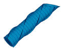
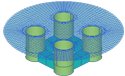
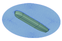
To illustrate these rules, Test05 in Appendix A includes a cylinder and spheroid, both with two planes of geometric symmetry and located at different positions on the global x-axis. However in TEST05 (also in TEST13) the spheroid is rotated 90∘ about the vertical axis, and this prevents the use of global symmetry. In the modified Test05a, the two bodies have the same relative orientations (since the cylinder is axisymmetric) but their centers are on the global y-axis to avoid rotation of the spheroid about its vertical axis. Thus in TEST05a the global symmetry indices are (1 0) and computational times are reduced substantially.
When NBODY>1 both the global symmetry and body symmetry for each body are output in the .OUT file.
8.6 OUTPUT
The nondimensionalizations given in Chapter 3 hold for all output quantities. L=ULEN(1), the dimensional length for Body 1, is the characteristic length and is used for the nondimensionalization of the output quantities.
The added mass (Aij), damping coefficients (Bij) and hydrostatic coefficients(C(i,j)) are matrices of dimension up to 6N × 6N. These quantities are defined in the direction of the axes of the corresponding body coordinate systems. For example A1,9 is the added mass in the direction of the x-axis of the coordinate system of Body 1 (surge added mass) due to the motion of the Body 2 in the direction of the z-axis of Body 2 (heave motion).
The forces (Xi) and the motion amplitudes (ξi) are vectors of dimension up to 6N. These quantities are also defined in the direction of the axes of the coordinates system of the corresponding body. For example, X17 is the pitch exciting moment about the y-axis of Body 3. The phases of the forces and motion amplitudes and of the field quantities such as the field pressure and field velocity, are defined relative to the phase of the incident wave at the origin of the global coordinate system.
The pressure drift force and moment (Option 9) returns values for each body in its respective body coordinate system.
When Option 8 is specified (momentum drift force and moment) the quantities calculated are the global horizontal drift forces and mean yaw moment acting on the entire ensemble of bodies. It is possible to compare these outputs with the total drift force and moment from pressure integration, by summing the latter outputs for the forces and moments on each body. This provides a useful check on consistency. Special attention is required if the body coordinates are not parallel to the global coordinates system.